2. Computer Aided Design (CAD)#
To begin, this second module is here to learn how to use different CAD (computer-aided design) software such as Inkscape, FreeCAD, and OpenSCAD. These software help us design 3D models of all sizes, depending on the suite and group, and we can 3D print the different parts we know and can associate.
| Feature/Aspect | Inkscape | FreeCAD | OpenSCAD |
|---|---|---|---|
| Primary Focus | 2D vector graphics | 3D parametric modeling | Code-based 3D design |
| Ease of Use | Intuitive GUI | Moderate GUI | Requires coding skills |
| Best For | Artistic design | Engineering & architecture | Mathematical designs |
| Output | 2D images (SVG, PNG) | 3D models (STEP, STL) | 3D models (STL, DXF) |
| Flexibility | High for 2D graphics | High for 3D design | High for parametric shapes |
| Skillset Needed | Artistic/Design skills | CAD and engineering | Coding skills |
2.1. Third class#
This week’s assignment is to design, model and document a FlexLinks parametric construction kit that will be manufactured by 3D printers. The model should be parametric so that adjustments can be made taking into account material properties and machine characteristics.
To meet the necessary requirements, I chose to use OpenSCAD, as I’ve worked with FreeCAD and other tools on previous projects, and I think it’s a good time to familiarize myself with this new software. Also, for these specific tasks, I think it will be much easier for me to parameterize the desired objects using code.
2.1.1. OpenSCAD#
First step is to install OpenSCAD to our machine, we can do that following this link OpenSCAD, here you can find the install for all the platforms.
Now that OpenSCAD is installed , it may be useful to have access to the OpenSCAD_doc. The documentation of a software is always very important, you can discover tools and also find the needed command for your code. I advice you to check the OpenSCAD tutorial by Nicolas De Coster. This was my starting point in discovering OpenSCAD and helped me a lot. There is also a cheat sheet available that contains the most basic and useful functions.
2.1.2. Designing a FlexiLink#
The objective is to design a flexilink, I chose to create this flexlink called “Satellite” Beam, which as you will see below has a small modification.
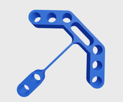
You can find more flexilink examples here.
2.1.3. Basic parts#
- The first part that forms the basis of the flexilink is the one that has holes so it can be combined with Lego, see a picture below.
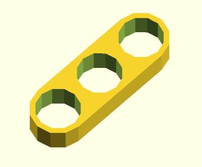
To achieve this geometry, I implemented two modules. The first, rounded_rectangle, generates a rectangular shape with rounded corners by means of the convex hull between two identical cylinders separated along the Y axis. The second module, holesPiece, constructs the final piece by applying a Boolean difference() operation between said base shape and a series of cylinders that act as holes. The number of holes is defined parametrically (n_holes), and each one is positioned at regular intervals determined by the outer radius (r_ext). It is essential that the radius of the subtracted cylinders (r_int) be smaller than r_ext, since the latter not only defines the rounding of the ends, but also the total width of the piece; otherwise, the holes would exceed the limits of the base geometry.
module rounded_rectangle(height, length, r) {
    hull() {
        cylinder(h = height, r = r, center = false, $fn = $fn_global);
        translate([0, length, 0])
            cylinder(h = height, r = r, center = false, $fn = $fn_global);
    }
}

module holesPiece(height, n_holes, r_int, r_ext) {
    length = r_ext * 2 * (n_holes - 1);
    difference() {
        rounded_rectangle(height, length, r_ext);
        for (i = [0 : n_holes - 1]) {
            translate([0, r_ext * 2 * i, 0])
                cylinder(h = height + 1, r = r_int, center = false, $fn = $fn_global);
        }
    }
}
- The next step is to make a component with a empty center, that later will be combined with our previous part.
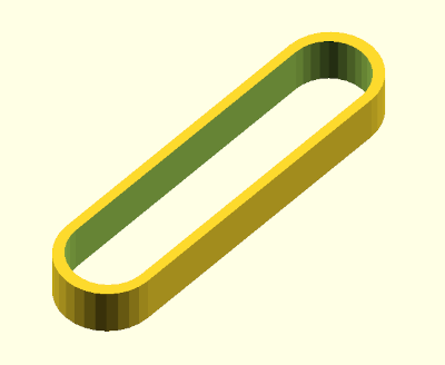
This second part is easily obtained using two modules. First, a rounded rectangle (rounded_bar) is defined, as previously done. Then, in the main module (symmetric_hollow), two of these shapes are generated: an outer one with radius r_ext and an inner one with radius r_int_side, but slightly shorter in length. The difference between the two is calculated so that the gap is centered, ensuring that the ends have a uniform thickness determined by r_ext - r_int_end. By applying the Boolean operation difference(), this hollow and symmetrical part is obtained.
module rounded_bar(height, length, r) {
    hull() {
        cylinder(h = height, r = r, center = false, $fn = $fn_global);
        translate([0, length, 0])
            cylinder(h = height, r = r, center = false, $fn = $fn_global);
    }
}

module symmetric_hollow(height, length, r_ext, r_int_side, r_int_end) {

    difference() {
        rounded_bar(height, length, r_ext);

        inner_length = length - 2 * (r_ext - r_int_end);

        offset_y = (length - inner_length) / 2;

        translate([0, offset_y, 0])
            rounded_bar(height, inner_length, r_int_side);
    }
}
- Near the end, I was designing this piece, inspired by the [Euler Catapult] (https://www.thingiverse.com/thing:6191651).
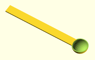
To achieve this geometry, a thin rectangular strip was created with cube() and a hollow hemisphere was added to one end. The hemisphere is formed by subtracting a smaller sphere from a larger one and cutting away its lower half. The strip is trimmed at its intersection with the inner cavity to ensure a clean, seamless connection.
2.1.4. Combined structure#
Now it’s time to combine the parts from the previous steps.
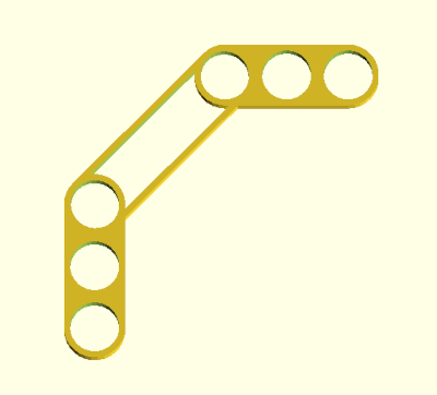
union() {
    translate([0, 0, 0])
        rotate([0, 0, 135])
            holesPiece(h, n, r_in, r_out);
    translate([0, arm_length, 0])
        rotate([0, 0, 45])
            holesPiece(h, n, r_in, r_out);
    translate([0,0,0])
        symmetric_hollow(
            height = h,
            length = r_out * 2 * n,
            r_ext = r_out,
            r_int_side = r_in,
            r_int_end = 4.8
        );
}
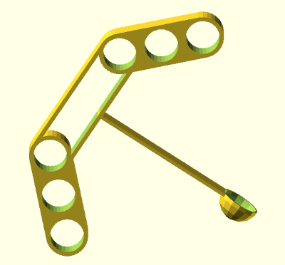
union() {
    piece_B();

    h = 5;
    r_out = 5;
    n = 3;
    arm_length = r_out * 2 * n;
    piece_length = r_out * 2 * (n - 1);

    translate([0, arm_length + piece_length, 0])
        rotate([90, 180, 0])
            mount_piece_A(offset_y_from_origin = arm_length, clearance_z = 5);
}
OpenSCAD’s union() function allows you to combine multiple geometries into a single solid object. To achieve a precise layout, each part is positioned using translate(), which defines its initial coordinates in 3D space; this is critical, as only with the correct coordinates will the desired configuration be achieved. Additionally, the initially created base part with holes is oriented as needed using rotate().
The entire code is created from modules, this is why it is a code that allows us to very easily modify the desired parameters for FlexiLinks.
2.1.5. Last parts#
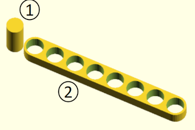
To complete my FlexiLink kit, I need Lego-like pieces. At this point, the design was pretty straightforward. For my kit, I’ll need four cylinders (piece 1) for the link and two bars (piece 2) for the base.
2.1.6. Licensing the work#
In open source, for others to be able to use our documentation or code, it’s essential to license our work. Here’s a link with more information about CC licenses (https://creativecommons.org/share-your-work/cclicenses/). The license I chose is CC BY-SA 4.0 (https://creativecommons.org/licenses/by-sa/4.0/). This license allows others to use and modify the code, as long as the author is acknowledged. It’s important to note that adaptations must be shared under the same terms. Here’s the example I used at the beginning of my code.
//File : FlexLink_dani.scad

// Author : Daniela Martinez

// License : This work is licensed under a Creative Commons Attribution-ShareAlike 4.0 International [CC BY-SA 4.0](https://creativecommons.org/licenses/by-sa/4.0/)
Although I did review other students’ documentation from past editions of the course, I didn’t use anyone’s code. However, I must emphasize that being able to access other students’ work is a great learning opportunity. I hope my work will also serve as a guide for future classmates.
Check-list#
- [X] parametrically modelled some FlexLinks using 3D CAD software
- [X] shown how you did it with words/images screenshots
- [X] included your original design files
- [X] included the CC license to your work
- [X] documented how you used other people’s work and gave proper credit to complete your kit