4. Electronic Prototyping#
In this part of the course, we could choose between four practical units: computer controlled cutting, computer controlled machining, electronic prototyping, or 3D printing for repair. I opted for the electronic prototyping unit because I know it will be a fundamental tool for my academic and professional development.
I am currently beginning my PhD in Bioengineering, and I now realize that these skills—working with microcontrollers, sensors, and embedded systems—will be necessary in almost all of my research. Furthermore, they will be key to the design and construction of my final project, in which I plan to develop devices capable of autonomously monitoring environmental variables, possibly installed on buoys in coastal areas.
But beyond my own path, this training has a collective purpose. As a Cuban research fellow in the ARES program, I have the unique opportunity to learn at the ULB and bring this knowledge back to Havana, where a FabLab will soon open within the framework of this cooperation project. What I’m learning in Brussels today won’t just be useful to me: it will become teaching material, shared prototypes, and, hopefully, solutions designed from and for Cuba.
4.1. Fifth class#
This class was a good practical introduction to the world of electronics: we reviewed fundamental theoretical concepts and put them into action using simple, accessible, and highly illustrative examples.
4.1.1. What is a microcontroller?#
During this course, we learned how to create electronic prototypes with an Arduino microcontroller. Microcontrollers are small, relatively inexpensive computers built on a single integrated circuit. They contain one or more CPUs, memory, and programmable input/output peripherals. Unlike microcomputers, they do not contain an operating system, which makes them much more responsive but limits them to relatively simple tasks.
The Arduino microcontroller we used is the Arduino UNO model and looks like this:

4.1.2. Electrical theory#
It’s necessary to understand some basic physics principles to avoid damaging the various components. Therefore, we’ve provided a refresher on amperage, voltage, and resistance.
Electric current is the flow of charge (measured in amperes, A) that carries energy through a circuit. For this flow to exist, the circuit must be closed: the charge leaves the power supply, passes through components (such as sensors, LEDs, or servos), and returns to the ground pin (GND), which acts as a common voltage reference point.
What drives the current is the potential difference, or voltage (measured in volts, V). We can think of it as an “electrical pressure” created by a source (battery, USB, etc.) that pushes the charge from a high potential point (e.g., 5 V) to a low potential point (0 V = GND).
Uncontrolled, the current can be too high and damage sensitive components. That’s why resistors are used, which limit the flow according to Ohm’s law:
I = V/R
Before connecting any device to the Arduino, it’s essential to check its maximum voltage and current specifications, and use resistors to ensure safe operation (Here is a link that helped me to determine the resistor value, needed when made the circuits).
4.1.3. How to program a microcontroller?#
Now that we’ve reviewed the basics of electrical theory, let’s talk a little more about Arduino.
The Arduino board contains a small computer that can start and stop current according to programmed instructions. For example, we can write instructions that tell the microcontroller to initiate a current for 1 second through output pin 3 every 10 seconds. If we connect the wires correctly to build a circuit that connects output pin 3 to ground and passes it through an LED, we will see a 1-second flash of light every 10 seconds.
What’s interesting is that we can also connect input devices and program instructions that depend on input currents. For example, the microcontroller could turn on a fan connected to an output pin if the thermometer connected to an input pin sends a signal corresponding to a high temperature, and many other examples like these.
These instructions can be written and sent to the Arduino board easily using a text editor called Arduino IDE.
Arduino IDE interface#
Before class, we must install Arduino IDE, which is available for your preferred platform. Programming in Arduino wasn’t difficult for me, although I had used it once for a very specific assignment. Overall, it was a new environment, but I managed to adapt quickly. Here is a useful guide on how to program your RP2040 microcontroller. Also the Arduino documentation and the built-in examples. The latter was very useful and helped me better understand how the Arduino IDE works. It also gave me the opportunity to try new things in addition to the assignments. You can also find these examples in the Arduino IDE by going to File > Examples. Initially, I used them to familiarize myself with the code and start communicating with the microcontroller.
Basic Example: Blink#
During this lesson, we were asked to explore the example files I mentioned earlier to understand basic Arduino syntax and libraries:

For example, by opening Files > Examples > Basics > Blink, we see a new window with the following code:
/*
  Blink

  Turns an LED on for one second, then off for one second, repeatedly.

  Most Arduinos have an on-board LED you can control. On the UNO, MEGA and ZERO
  it is attached to digital pin 13, on MKR1000 on pin 6. LED_BUILTIN is set to
  the correct LED pin independent of which board is used.
  If you want to know what pin the on-board LED is connected to on your Arduino
  model, check the Technical Specs of your board at:
  https://docs.arduino.cc/hardware/

  modified 8 May 2014
  by Scott Fitzgerald
  modified 2 Sep 2016
  by Arturo Guadalupi
  modified 8 Sep 2016
  by Colby Newman

  This example code is in the public domain.

  https://docs.arduino.cc/built-in-examples/basics/Blink/
*/

// the setup function runs once when you press reset or power the board
void setup() {
  // initialize digital pin LED_BUILTIN as an output.
  pinMode(LED_BUILTIN, OUTPUT);
}

// the loop function runs over and over again forever
void loop() {
  digitalWrite(LED_BUILTIN, HIGH);  // turn the LED on (HIGH is the voltage level)
  delay(1000);                      // wait for a second
  digitalWrite(LED_BUILTIN, LOW);   // turn the LED off by making the voltage LOW
  delay(1000);                      // wait for a second
}
Let’s stop a bit and take some time to understand the code. The latter can be divided in four parts :
- The comment:
It is bounded by the
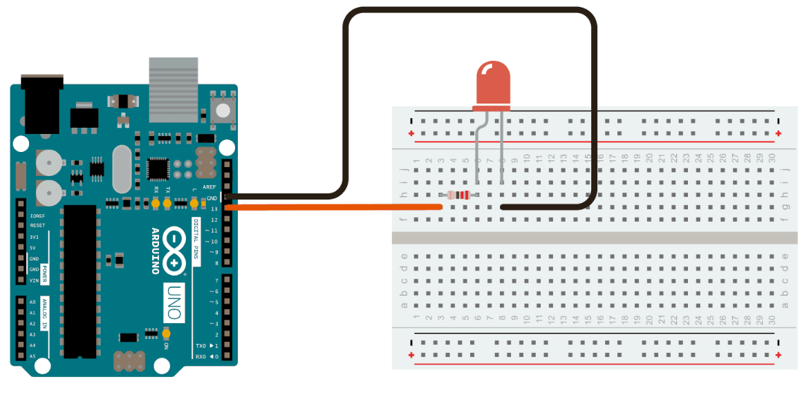
/**/characters. It explains what the code does and how to construct the right circuit in order to make it works. There is also an link (https://docs.arduino.cc/built-in-examples/basics/Blink/) where we can find more detailed explanations on how to build the circuit and even an image of it:
-
Variable Definitions: These lines are the only uncommented lines not included within a function. They define global variables that will be used frequently in functions. This is where pin variables should be defined. If we want Arduino to control or read a signal from a device, it needs to know which output/input it’s connected to. Therefore, these pin numbers will be used frequently in the code, and it’s always easier to assign them a name.
-
The
setup(): This is the place where one actually communicates to the microcontroller which pin is an output or input using the functionpinMode. As mentioned earlier, we can also write code that executes only once when the microcontroller receives the instructions. -
The
loop(): This is the main part of the code, containing the instructions that will be repeated for the microcontroller to function correctly.
4.2. Sixth class: DHT20 - Temperature & RH sensor#
In order to work with the sensor DHT20 , it’s required to read the datasheet and also as part of assignment is to identify relevant characteristics.
On the data sheet you can find a lot of informations. The ones we will use are :
-
The sensor specifications
-
The expansion performance
-
The interface definition
-
The electrical characteristics
For now, let us have a look to the interface definition section. We can find the following pictures explaining what are each pins.
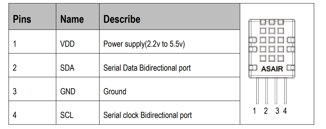
It’s easy to understand that we must connect the power supply to the first pin and the ground to the third. These must also be connected to the SDA pin (which sends the data: temperature and humidity measurements) and the SCL pin (which synchronizes the microcontroller with the sensor) on the Arduino board, respectively.
We’re almost ready to connect the sensor, but first we must verify its electrical characteristics to check for compatible maximum voltage and current values.
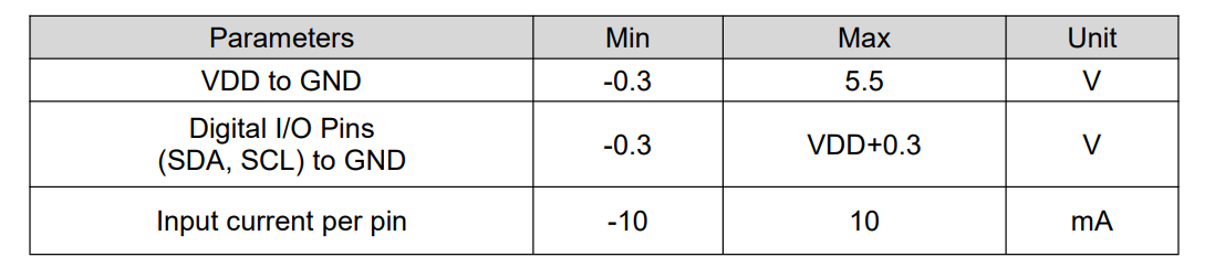
Taking everything into account so far, we can now connect everything and obtain:
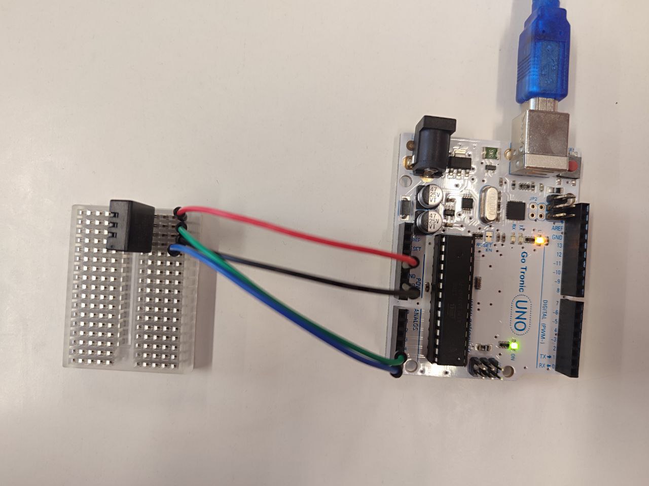
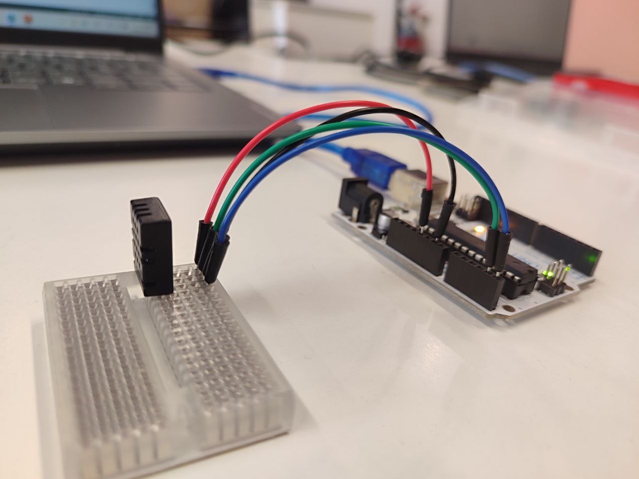
We are now ready to read the data measured by the sensor ! Let’s get back on the IDE.
4.2.1. DHT20 Library#
You need to install the library for the DHT20 sensor. To do this, in the Arduino IDE, go to Sketch > Include Library > Manage Libraries; then, using the search bar, find the DHT20 library and install it.
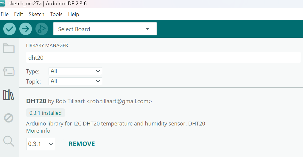
We now also have access to code examples related to the DHT20. To test the temperature and humidity sensor, we used the existing code located in File > Examples > DHT20 > DHT20_plotter. The code is as follows:
//
//    FILE: DHT20_plotter.ino
//  AUTHOR: Rob Tillaart
// PURPOSE: Demo for DHT20 I2C humidity & temperature sensor
//     URL: https://github.com/RobTillaart/DHT20
//
//  Always check datasheet - front view
//
//          +--------------+
//  VDD ----| 1            |
//  SDA ----| 2    DHT20   |
//  GND ----| 3            |
//  SCL ----| 4            |
//          +--------------+


#include "DHT20.h"

DHT20 DHT(&Wire);


void setup()
{
  Wire.begin();
  DHT.begin();  //  ESP32 default pins 21 22

  Serial.begin(9600);
  Serial.println("Humidity, Temperature");
}


void loop()
{
  if (millis() - DHT.lastRead() >= 1000)
  {
    //  note no error checking
    DHT.read();
    Serial.print(DHT.getHumidity(), 1);
    Serial.print(", ");
    Serial.println(DHT.getTemperature(), 1);
  }
}


//  -- END OF FILE --
Below is the result obtained after the code has been running for a while:
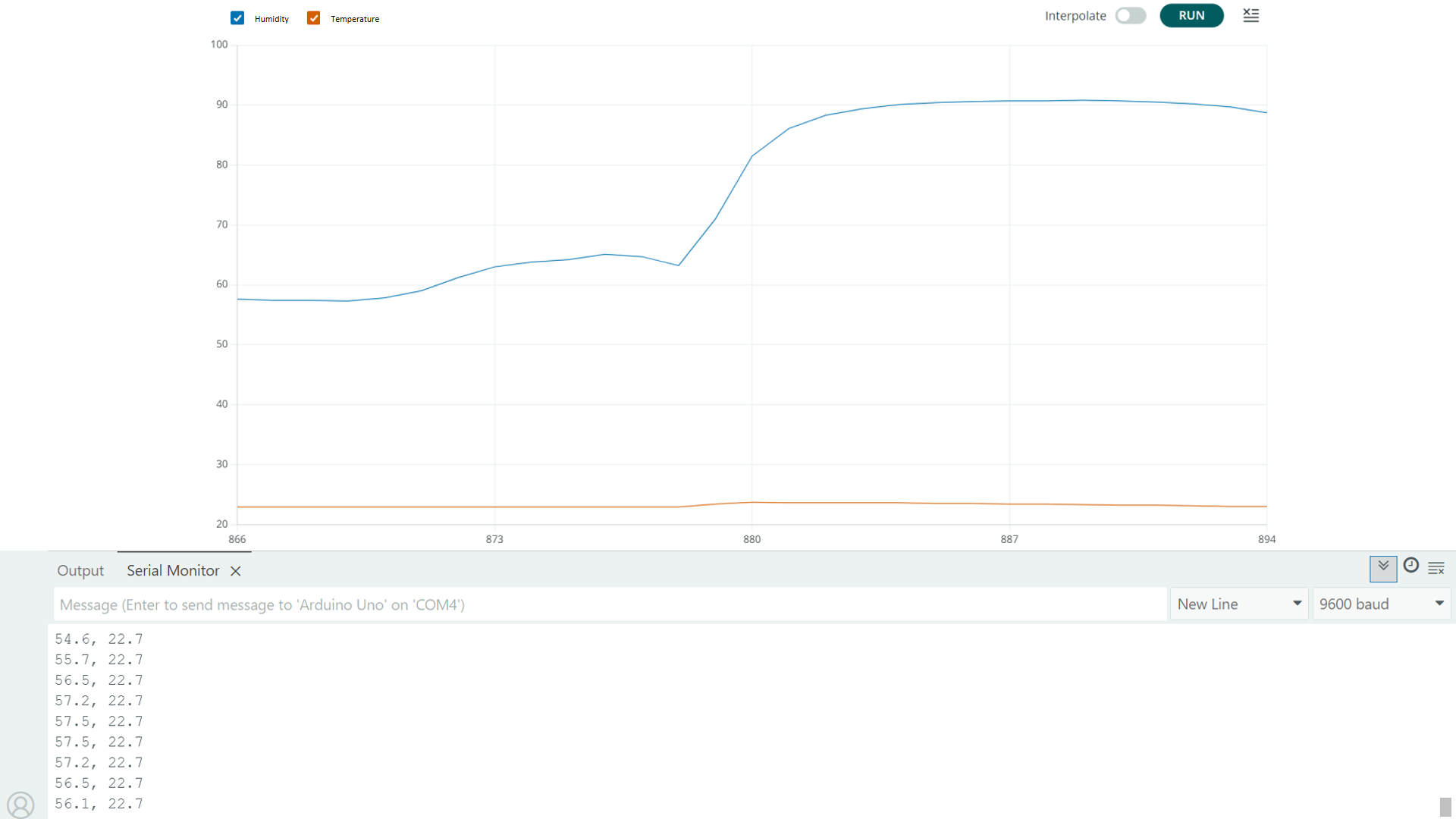
As I blow with heat in the sensor, we can observe changes in the humidity and temperature.
4.2.2. DHT20 with onboard LED#
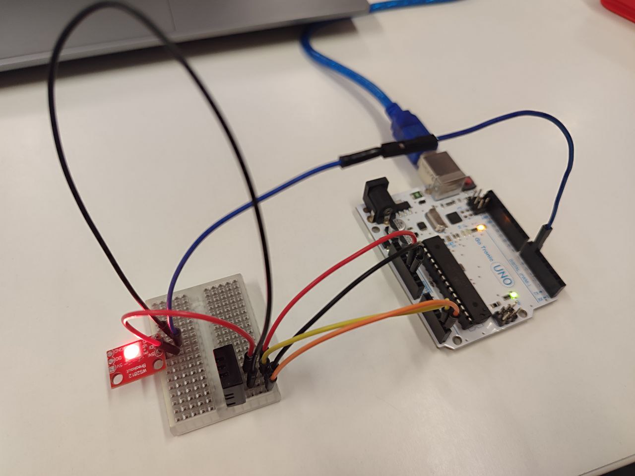
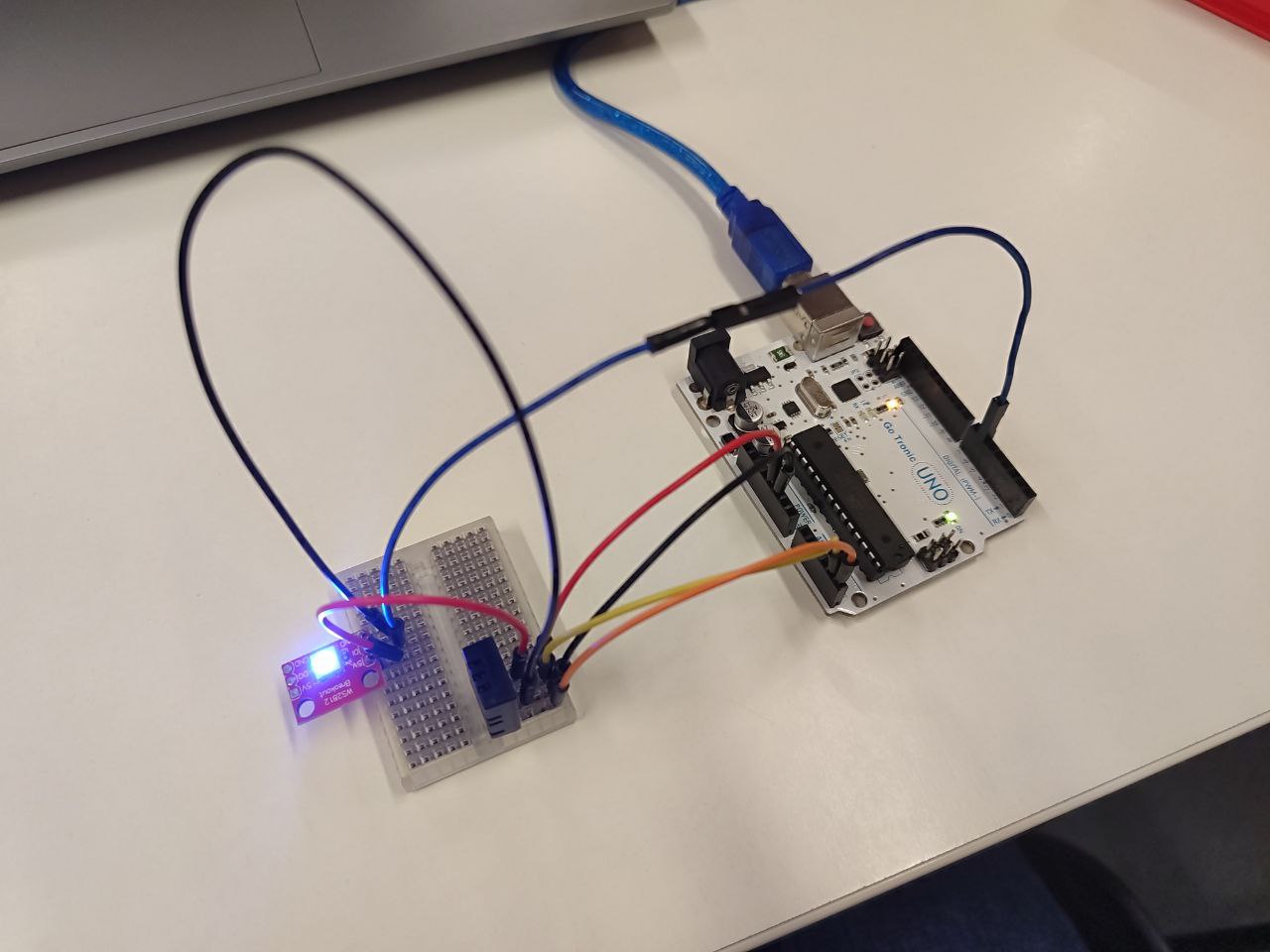
Now, I’ll add an LED to my board that lights up red when the temperature exceeds 24°C and blue if it’s below or equal to that temperature. To work with this type of LED, I installed the Adafruit_NeoPixel library. The procedure is similar to that of the DHT20.
Below, you’ll find the code I created and an image of the circuit.
//File : DHT20_led.ino

// Author : Daniela Martinez

// License : This work is licensed under a Creative Commons Attribution-ShareAlike 4.0 International [CC BY-SA 4.0](https://creativecommons.org/licenses/by-sa/4.0/)

#include "DHT20.h"
#include <Adafruit_NeoPixel.h>
#define PIN        6

Adafruit_NeoPixel pixels(1, PIN, NEO_GRB + NEO_KHZ800);

DHT20 DHT(&Wire);


void setup()
{


  Wire.begin();
  DHT.begin();

  Serial.begin(9600);
  Serial.println("Humidity, Temperature");
  pixels.begin();
}


void loop()
{
  if (millis() - DHT.lastRead() >= 1000)
  {
    pixels.clear();

    //  note no error checking
    DHT.read();
    Serial.print(DHT.getHumidity(), 1);
    Serial.print(", ");
    Serial.println(DHT.getTemperature(), 1);

    if (DHT.getTemperature() > 24.0)
    {
      pixels.setPixelColor(0, pixels.Color(255, 0, 0));
      }
      else {
        pixels.setPixelColor(0, pixels.Color(0, 0, 255));
      }

    pixels.show();
  }
}
//  -- END OF FILE --
4.2.3. Challenge#
For the challenge, I added a servo motor to my circuit. The idea is that when the LED lights up red (temperature above 24°C), the servo motor rotates 90° from its starting position, and when the temperature drops (blue LED), the motor returns to its starting position. This is the code I wrote:
//File : DHT20_led.ino

// Author : Daiela Martinez

// License : This work is licensed under a Creative Commons Attribution-ShareAlike 4.0 International [CC BY-SA 4.0](https://creativecommons.org/licenses/by-sa/4.0/)

#include "DHT20.h"
#include <Adafruit_NeoPixel.h>
#include <Servo.h>  // <-- NUEVO: librería para servo

#define LED_PIN   6
#define SERVO_PIN 9  // pin para el servo

Adafruit_NeoPixel pixels(1, LED_PIN, NEO_GRB + NEO_KHZ800);
DHT20 DHT(&Wire);
Servo miServo;  // <-- NUEVO: objeto servo

void setup() {
  Wire.begin();
  DHT.begin();
  miServo.attach(SERVO_PIN);  // <-- NUEVO: inicia el servo en pin 9

  Serial.begin(9600);
  Serial.println("Humidity, Temperature");
  pixels.begin();

  // Posición inicial del servo (ej. 0°)
  miServo.write(0);
}

void loop() {
  if (millis() - DHT.lastRead() >= 1000) {
    pixels.clear();
    DHT.read();

    float temp = DHT.getTemperature();
    float hum = DHT.getHumidity();

    Serial.print(hum, 1);
    Serial.print(", ");
    Serial.println(temp, 1);

    if (temp > 24.0) {
      pixels.setPixelColor(0, pixels.Color(255, 0, 0)); // rojo
      miServo.write(90);  // <-- mueve el servo a 90° (ej. "alarma activada")
    } else {
      pixels.setPixelColor(0, pixels.Color(0, 0, 255)); // azul
      miServo.write(0);   // <-- vuelve a posición inicial
    }

    pixels.show();
  }
}
//  -- END OF FILE --
As you can see in the following video, the result is as expected:
Check-list#
- [X] documented what you have learned from interfacing input devices to a micro controller and how the physical property relates to the measured results
- [X] documented what you have learned from interfacing an output device to a micro controller and controlling the device
- [X] programmed your board
- [X] described your programming process
- [X] outlined problems and how you fixed them
- [X] included original design files and source code
- [X] included a “hero shot/video” of your board in operation